How structural steel beams are fabricated: from raw steel to site-ready

Most builders who order steel beams regularly have a clear idea of what they need and what they expect to receive. What many are less familiar with is what actually happens between placing the order and the beam arriving on a flatbed at the site gate. Understanding the fabrication process is not just interesting for its own sake. It helps builders ask better questions when ordering, understand why certain details need to be specified at order stage, and appreciate why some jobs take longer than others.


This guide walks through the structural steel fabrication process from the raw material stage through to a finished, site-ready beam, drawing on the way we work at our Horbury Junction workshop in Wakefield. It covers steel grades, section types, cutting, drilling, welding, surface preparation and finishing, and the quality checks that happen along the way.

How structural steel sections are made

Before a beam arrives at a fabrication workshop, it has already been through a significant manufacturing process at a steelworks. Structural steel sections are produced by hot rolling: a process in which a large billet of steel is heated to around 1,200 degrees Celsius and then passed repeatedly through a series of rolling mills that progressively shape it into the required profile.


Universal beams, universal columns, parallel flange channels and other standard sections are all produced this way. The rolling process gives each section its characteristic shape, with the I-section profile of a universal beam resulting from the geometry of the rolling mills used to produce it. Once rolled to the required section, the steel is cut into standard lengths, typically 12 or 18 metres, and allowed to cool. It is then straightened, inspected and bundled for despatch to stockholders and fabrication workshops.


The finished sections arrive at our workshop in standard mill lengths, still covered in a thin layer of mill scale from the hot rolling process. From this point, the fabrication process begins.

Steel grades: S275 and S355

Not all structural steel is the same. The steel used in structural sections is produced to specific grades that define its mechanical properties, most importantly its yield strength. The two grades most commonly specified for structural work in the UK are S275 and S355.


S275

S275 is the most commonly used structural steel grade for domestic and light commercial applications. The 275 refers to its minimum yield strength of 275 megapascals. S275 is available in all standard structural sections and is the default specification for most domestic wall removal, extension and loft conversion projects. It offers a good balance of strength, weldability and cost.


S355

S355 has a higher minimum yield strength of 355 megapascals, making it approximately 30 percent stronger than S275 for a given cross-section. It is specified where higher loads need to be carried, where a lighter or shallower section is required than S275 would allow, or where the structural engineer has specifically called for it. S355 costs slightly more than S275 and is used less frequently in standard domestic work, but it is readily available and we stock both grades at our Wakefield workshop.


When ordering steel, always specify the grade called for on the structural engineer's drawings. Do not assume that S275 is always adequate or that S355 can always be substituted. The structural calculations are based on a specific grade and substituting a different one without the engineer's approval is not acceptable.

The range of sections available

Structural steel fabricators work with a range of different section types, each suited to different structural applications. Understanding the available sections helps builders and clients communicate clearly about what they need.


Universal beams (UB)

Universal beams, often referred to as RSJs in the domestic market even though this is not strictly accurate, are the most widely used structural section in building construction. They have a characteristic I-shaped cross-section with wide flanges relative to their depth. The designation follows the format depth x flange width x weight per metre, so a 203x102x23 UB is 203mm deep, 102mm wide at the flanges, and weighs 23 kilograms per linear metre. Universal beams are primarily designed to resist bending loads and are the standard section for spanning openings in walls and supporting floor and roof structures.


Universal columns (UC)

Universal columns have a similar I-section to universal beams but with proportionally wider flanges relative to their depth, making them well suited to carrying compressive loads as vertical members. They are used as columns, posts and props in structural frames, and are sometimes specified as horizontal members where the greater flange width is useful for connection details. A 152x152x23 UC, for example, has almost equal depth and flange width, giving it a more square profile than a universal beam of similar weight.


Parallel flange channels (PFC)

Parallel flange channels have a C-shaped cross-section with two flanges projecting from one side of a web. They are used where a beam needs to sit flush against a wall or another section on one side, where a box or twin-beam arrangement is being created, or in flitch beam configurations with timber. PFC sections are specified regularly in loft conversions and roof structures where the geometry of the installation requires a section that can be positioned against a wall face.


Angles, flat bar and plate

Angles, flat bar and plate are used for a range of secondary structural and connection purposes. Angles are used for cleats, brackets and as light structural members in their own right. Flat bar is used for connections, packing pieces and minor structural details. Plate is used for gussets, base plates, end plates and other connection components that are welded to primary structural sections. We cut, drill and weld all of these at our Wakefield workshop as part of the fabrication service.

The fabrication process step by step

Step 1: Receiving and checking the material

When steel sections arrive at the workshop from the stockholder, the first step is checking that the material received matches the order. Section designation, grade, length and quantity are all checked against the delivery documentation. Any discrepancy is flagged before fabrication begins. Using the wrong section grade or size because of an unchecked delivery error is a problem that is much easier to catch at this stage than after the material has been cut.


Step 2: Marking out

Before cutting or drilling begins, the relevant dimensions are transferred from the structural drawings to the steel. Each section is marked with the overall fabricated length, the positions of any holes to be drilled, the locations of any welded connections, and any other details needed during fabrication. Clear and accurate marking at this stage is the foundation for accurate fabrication throughout the rest of the process.


Step 3: Cutting to length

Structural steel sections are cut to the fabricated length using a bandsaw or circular saw. The cut needs to be square, accurate and clean. At our Wakefield workshop we use a KALTENBACH KBS 1001 DG, an automated sawing and drilling line that handles both cutting and drilling operations to precise tolerances. This type of equipment allows consistent, repeatable accuracy across a batch of beams, which is important when multiple beams in a project need to be the same length or when hole positions need to be consistent across a series.

The cutting operation produces a clean, square end that is checked against the specified dimension before the section moves to the next stage. Off-cuts are retained for use in connection details or removed from the workshop.


Step 4: Drilling

Most structural beams require holes to be drilled for bolted connections, end plates or other connection details. The hole positions are specified on the structural engineer's drawings and are dimensioned from a datum, typically the end of the beam or the centre of the section. Holes are drilled to the diameter specified on the drawing, which is typically 2mm larger than the bolt diameter to allow for fit-up tolerance on site.

Getting hole positions right is critical. A hole that is in the wrong position means a connection that does not line up, which causes significant problems on site. On the KALTENBACH line, hole positions are programmed directly from the drawing dimensions, which eliminates the manual marking and hand drilling errors that can occur when holes are drilled by a less automated method.


Step 5: Welding connection details

Many structural beams require welded connection details: end plates at each end for bolted connections to other sections, stiffeners welded within the section at the bearing points, cleats for connecting secondary beams, or base plates for column sections. These are fabricated from plate, flat bar or angle cut to size, positioned carefully on the beam, and welded by our skilled welding team.

The quality of the welds on structural connections matters. Welds need to be of adequate size, fully fused and free from defects such as undercut, porosity or lack of fusion. All welding at our workshop is carried out to the engineer's specification and checked visually before the beam moves to the surface preparation stage. For critical welds on heavily loaded connections, more detailed inspection methods such as dye penetrant testing can be carried out where specified.


Step 6: Shot blasting

Shot blasting is the surface preparation process that removes mill scale, rust, welding spatter and any other surface contamination from the steel, leaving a clean, bright surface with a consistent anchor profile ready for protective coating. All steel that leaves our Wakefield workshop is shot blasted as standard, to Sa 2.5 standard under the ISO 8501-1 classification.


Sa 2.5 is the near-white metal cleanliness grade and is the standard required before most structural protective coatings are applied. Achieving this level of cleanliness requires the shot blasting media to be propelled at the steel surface with sufficient velocity and for a sufficient period to remove all mill scale and contamination. The result is a uniformly grey, slightly textured surface that provides an excellent key for coatings.


Shot blasting must be followed promptly by the application of a protective coating, because the cleaned surface will begin to re-rust in humid conditions within hours if left unprotected. At our workshop the beam moves from the shot blast cabinet directly to the coating stage.


Step 7: Applying the finish

Once shot blasted, the beam receives its specified protective finish. The most common finishes we apply are as follows.


Primer: A coat of protective primer is applied by brush or spray immediately after shot blasting. Primer seals the surface, provides a base for further painting on site, and protects the steel during transport, storage and installation. This is the standard finish for structural steel that will be concealed within the finished building.


Powder coat: For steel that will remain visible in the finished space, powder coating provides a hard, durable factory finish in any RAL or BS colour. The shot-blasted steel is coated with electrostatically charged paint powder and then cured in an oven. Powder coating requires the colour and finish type to be confirmed at the time of ordering.


Hot-dip galvanising: For steel that will be exposed to the elements or installed in damp environments, hot-dip galvanising provides the most durable long-term corrosion protection. The steel is immersed in molten zinc, which reacts with the steel surface to form a metallurgically bonded protective layer. Galvanising is typically carried out by a specialist subcontractor.


Step 8: Checking and labelling

Before any beam leaves the workshop, it is checked against the order. The fabricated length, hole positions, welded details and finish are all verified against the structural drawings and the order confirmation. Each beam is labelled with a reference that corresponds to the drawing, so that on site the installer can identify exactly which beam goes where without ambiguity. This is particularly important on larger projects where multiple beams of different sizes are delivered together.


Step 9: Loading and delivery

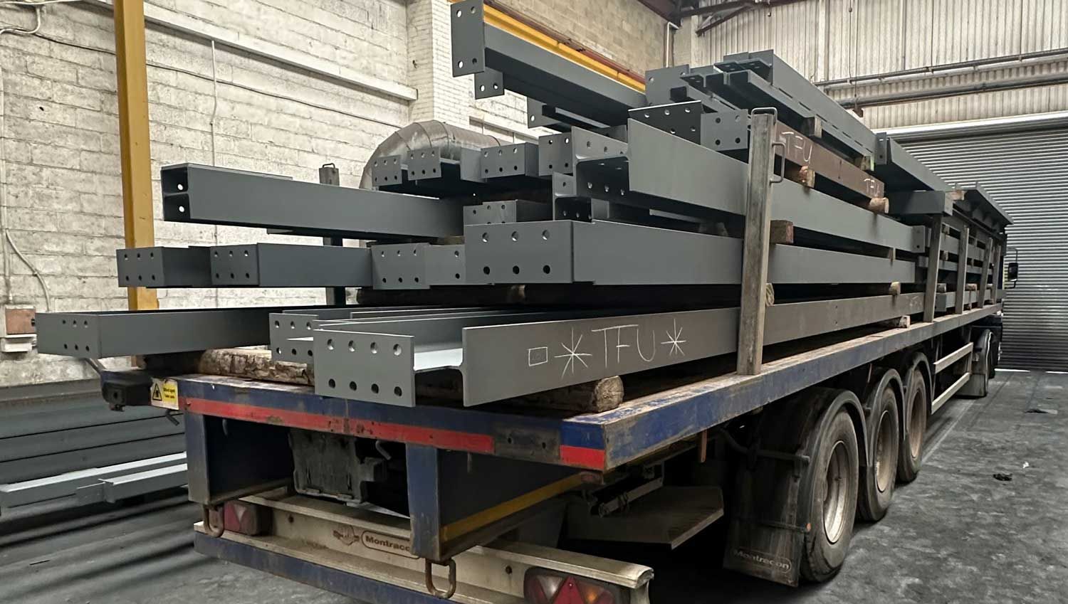
Finished beams are loaded onto the delivery vehicle with care to avoid damage to the finish. Beams are separated with timber dunnage to prevent contact between sections during transit, which would otherwise cause surface damage to primer or powder coat. The delivery is scheduled to suit the site programme and the vehicle is matched to the access conditions at the delivery address.


The difference between a stockholder and a fabricator

It is worth clarifying the distinction between a steel stockholder and a steel fabricator, because the two are sometimes confused.


A stockholder holds stock of standard steel sections in standard lengths and supplies them cut to a standard length or to a simple cut length without further processing. If you order from a stockholder, you typically receive a length of steel that still needs to be drilled, have connection details welded on, and be surface treated before it can be installed. The labour to do this either falls to the builder on site or needs to be arranged separately.


A fabricator, which is what we are at Builders Beams R Us, takes the raw section and produces a finished, site-ready beam from it. The cutting, drilling, welding of connection details, shot blasting and finishing are all done before the beam leaves the workshop. When our steel arrives on site, it is ready to install. There is no additional work for the builder to carry out, which saves time and reduces the risk of errors arising from on-site drilling or fabrication.


For domestic building projects, ordering from a fabricator rather than a stockholder is almost always the right approach. The additional cost of fabrication is modest relative to the overall project cost, and the benefit of receiving a finished, accurate beam that installs cleanly the first time is significant.

What to provide when ordering fabricated steel

Getting the order right from the start makes the fabrication process faster and produces a better result. When placing a steel order with us, the following information ensures we can fabricate accurately and efficiently.


  • The structural engineer's drawings: These are the primary document for fabrication. They show the section designation, the fabricated length, all hole positions and dimensions, any welded connection details, and the finish required. If the drawings are finalised, send them when you order.
  • The steel grade: Confirm whether S275 or S355 is specified. If the drawings do not specify a grade, ask the engineer before ordering.
  • The finish required: Primer, powder coat (with RAL colour reference if applicable), galvanising, or shot blast only. The finish needs to be confirmed at order stage, not as an afterthought.
  • The delivery postcode and preferred week: This allows us to schedule the delivery and confirm any access requirements in advance.

If you have questions about the fabrication process, the sections available, or what information is needed for a particular project, call us on 07301 033 581 or email contact@buildersbeamsrus.co.uk. We are happy to talk through the details before you place an order. All fabrication is carried out in-house at our Horbury Junction workshop in Wakefield, and we supply builders, contractors and developers across Yorkshire and the wider UK.

Recent Posts

Person building a wall
By Joe Holdsworth • September 18, 2026
What are building regulations, when do they apply, and how does the approval process work? A practical guide for builders and homeowners planning construction work in England.
House with detached garage
By Joe Holdsworth • August 21, 2026
A practical guide to garage conversions covering planning, building regulations, structural steel, insulation, services and common mistakes to avoid.
Open plan kitchen
By Joe Holdsworth • August 7, 2026
Planning an open plan kitchen diner? Our practical guide covers loadbearing walls, structural steel, temporary propping, building regulations and what to expect on site.
House extension project
By Joe Holdsworth • July 24, 2026
A practical guide to planning permission for home extensions. Covers permitted development rights, when full planning is needed, common refusals and how planning affects the structural design.
Party wall in a building site
By Joe Holdsworth • July 10, 2026
A practical guide to the Party Wall Act 1996 for builders working on extensions and loft conversions. Covers notices, surveyors, awards and how party walls affect your programme.
structural engineers looking at a drawing
By Joe Holdsworth • June 26, 2026
A practical guide for builders on getting the most from their structural engineer, from when to appoint one to how to brief them and how to use their drawings on site.
Converted loft
By Joe Holdsworth • June 12, 2026
Wondering what the steel will cost for your loft conversion? Our guide explains the factors that affect price, from section size and span to finish, so you can budget with confidence.
Steel Staircase
By Joe Holdsworth • May 29, 2026
Thinking about a steel staircase for a loft conversion, extension or commercial project? Our guide covers design, specification, building regulations, finishes and lead times.
Load of steel ready for delivery
By Joe Holdsworth • May 15, 2026
A practical site preparation checklist for builders ahead of steel beam delivery and installation. Covers access, propping, bearings, handling and what to confirm before your steel arrives.
completed loft conversion
By Joe Holdsworth • May 1, 2026
Yorkshire's Victorian terraces, stone houses and back-to-backs present unique steel challenges for loft conversions. A practical guide from our Wakefield fabrication workshop.
Show More